The valve train
Even if this is actually part of the primordial ooze of the first grade, we still need to talk briefly about the valve train in and of itself. Yet “valve train” is a beautiful, old-fashioned and typical engineering noun. Roughly like “chain drive” or “drive train”.
In any case, it refers to the technology that opens and closes all the valves in the cylinder head of the engine at the right time. And even if there have been 1001 bizarre valve curiosities in over 100 years of engine construction, the simple poppet valves that control the flow of fresh gas and exhaust gas in the head have prevailed. And the “valve train” is precisely the drive for these valves.
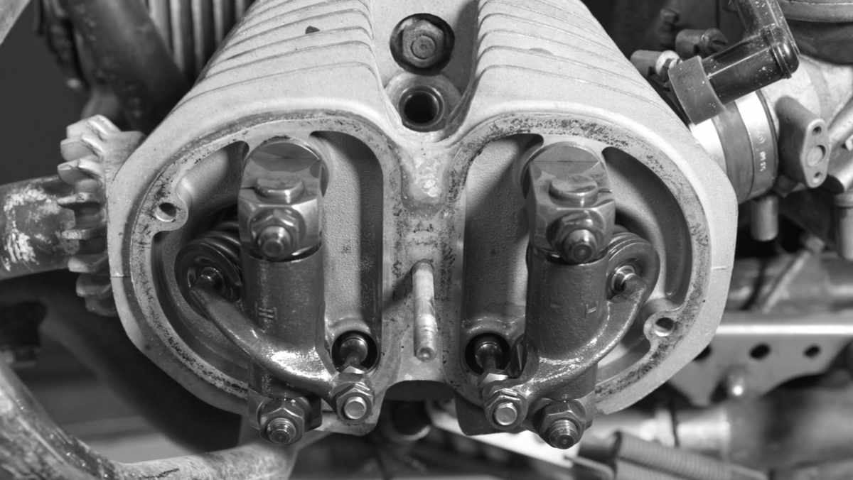
A widespread design consists of a camshaft, pushrods and rocker arms, like the old BMW in the picture below. The camshaft supplies not only the energy but also the timing and transmits both to the pushrods. Their up and down movement is transferred back to the valves by rocker arms.
https://de.wikipedia.org/wiki/Ventiltrieb
It doesn’t matter whether an engine has two, three or four valves per cylinder for our adjustment work. It doesn’t matter whether the camshaft is under the cylinder, next to it or in the cylinder head. Whether the camshaft is moved by gear, chain or belt and the engine runs as a diesel, petrol or gas engine is equally irrelevant. And whether it’s in a car, motorcycle, battle tank or wheelchair – it doesn’t matter. The valve actuator is always, always and always mechanical and must therefore fulfill a few requirements.
Correct timing
Requirement number one is quite simple: The timing must be correct. “Control time” means the time that the valves should be open and the time that they should be closed. Clearly, the intake valve should be tight when the piston compresses the cylinder contents and the big bang is imminent. And the exhaust valve should not open too early, so that the energy of the explosion is optimally utilized. The timing is a matter for the camshaft: the valve train merely transmits what the engineers have thought up and coded in the form of the cams. Opening too early or closing too late costs performance and fuel at this point.
Requirement number two does not cost any fuel, but it does cost lifetime: the valves must be closed for a sufficiently long time. After all, it is quite warm in the combustion chamber. So hot, in fact, that turbochargers glow and exhaust manifolds are wrapped in heat protection mats so that the car doesn’t accidentally flare up when towing a trailer in the Alps.
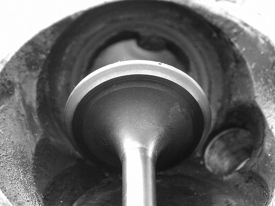
Under such infernal conditions, the valves in the cylinder head would also glow and burn a little later if they were unable to transfer their heat to the cylinder head. The majority of this “valve cooling” does not take place via the stem, but via the valve seat. As described in the article on grinding in the valves, this seat not only seals the intake or exhaust duct, but also ensures heat transfer when the valve is closed. The exhaust valve in particular is naturally subjected to higher loads in the engine and quickly turns into a charred shish kebab on a hot highway stage if it cannot get rid of its heat. The valves must therefore not only open correctly, but also be closed long enough.
Adjusting: Why?
The crankshaft, pistons and camshaft do not need to be adjusted. Simply because there is nothing to adjust here; the vast majority of combustion engine components are designed to the correct dimensions in the factory, fitted and then assembled. That’s it.
This would actually be the same for intake and exhaust valves. But only actually – because in the ugly reality, the forces and thus the wear on the valves are so great that the sealing surfaces “work themselves into” each other and the valves slip deeper into their seats over the course of hundreds of operating hours. This automatically reduces the clearance at the other end of the valve and the timing changes in the direction of “valve opens earlier and closes later”.
So anyone who disappears into the workshop with the feeler gauge and “adjusts the valves” is in some miraculous way bringing the clearance in the valve train to a value intended by the design – nothing more.
Adjusting the valves – simplest case
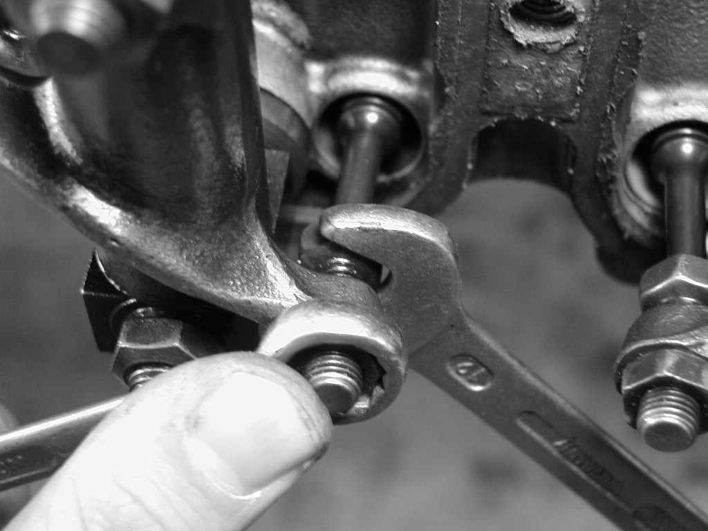
The valve train of this old BMW is representative of all simple valve trains on our planet: A bottom-mounted camshaft sets pushrods in motion, the pushrods actuate rocker arms and thus open the exhaust and intake valves. Coil springs close the valves again. Life can be that simple!
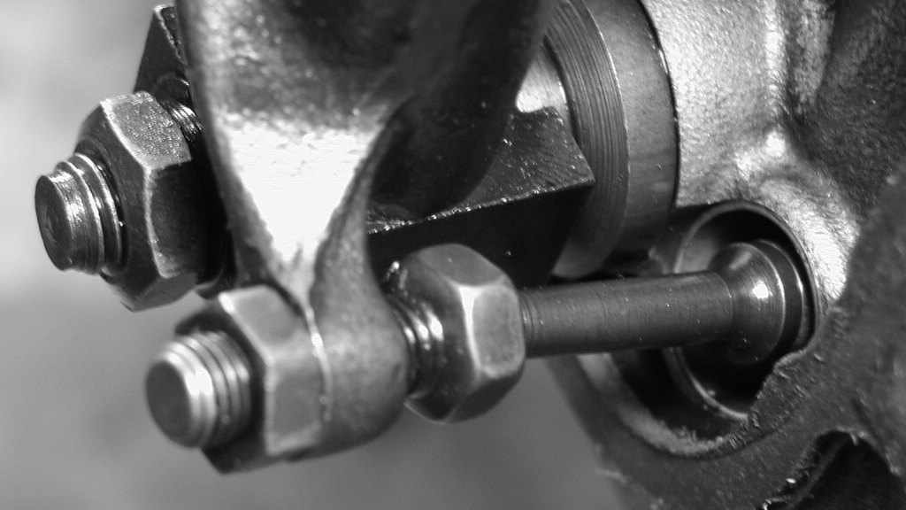
Bavarian engineers have installed an adjusting screw in each rocker arm to set the play in this folding mechanism: This is used to set the play to the desired value. To prevent the adjusting screw from loosening during operation, it is secured against turning with a lock nut. To adjust the valve clearance, all you need is a feeler gauge, the correct setting dimensions and something to turn the crankshaft in the engine.
Setting tool
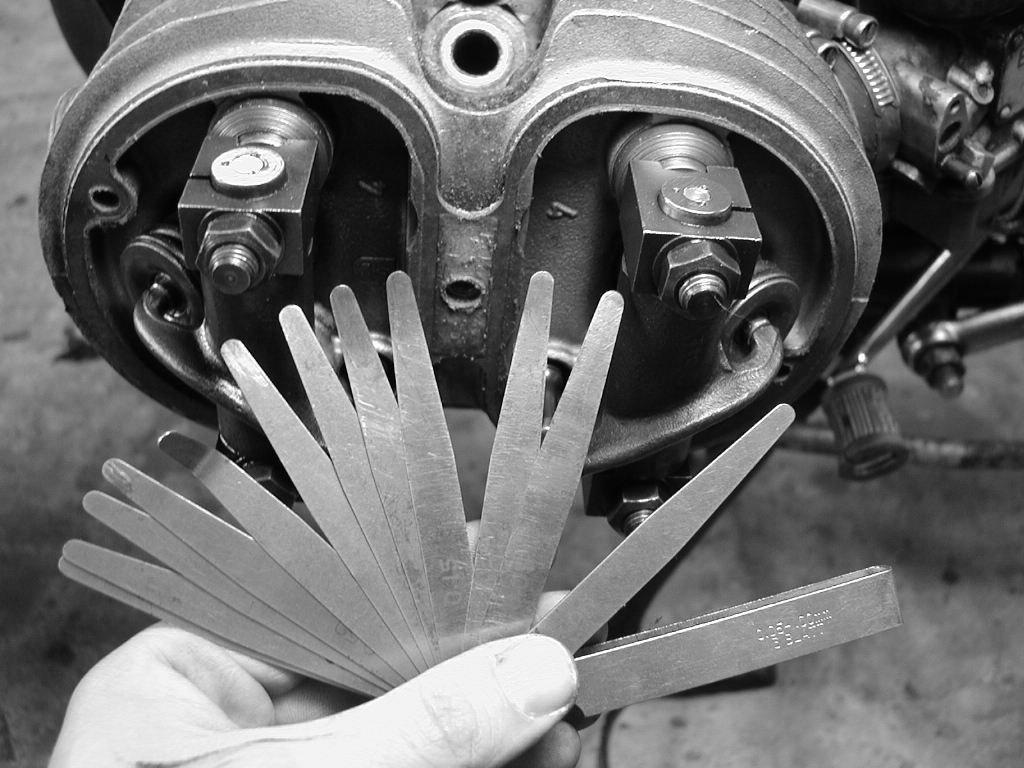
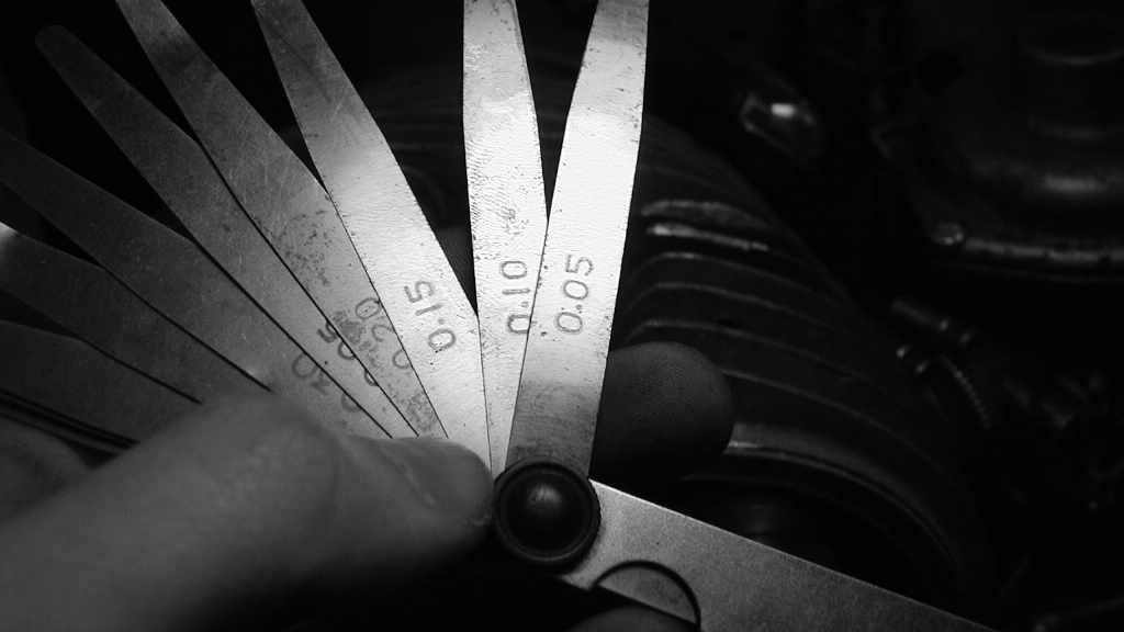
A “feeler gauge” or “feeler blade gauge” or “spy” or whatever is basically just a little booklet with steel tongues of different thicknesses for the purpose of setting valves. These things are sold by Master Wu for cents and are good even in the cheapest class.
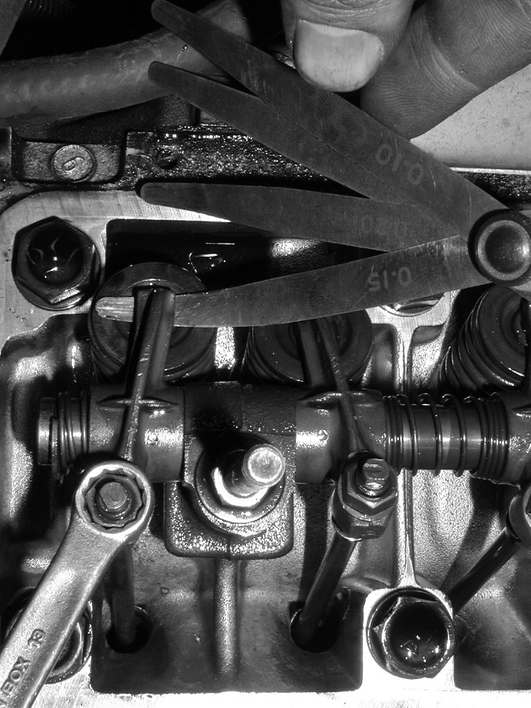
The feeler gauges in the picture are graduated as follows: 0.1 mm … 0.15 mm … 0.2 mm … and so on up to 2 mm. Even if the typical valve clearances are usually somewhere between 0.1 and 0.3 mm, this is easy to adjust – after all, you can simply place the leaves on top of each other and add up the dimensions.
Target values or setting dimensions
The setting dimensions for the motor can typically be found in the original manufacturer’s literature or in the depths of the internet. Because the exhaust valve in the cylinder head always feels the greater temperatures, its clearance is almost always tolerated to be greater than that of the intake valve. And as already discussed above, this clearance is also the more important of the two: A “hanging” exhaust valve becomes a coke spit in a flash, while the intake valve is always also cooled by the incoming fresh gas.
The values of e.g. 0.1 mm for the intake and 0.2 mm for the exhaust in the literature generally (!) refer to a cold engine. This is actually strange, as the clearance should be set correctly when the engine is warm. However, this simply cannot be done in practice when the machine is at operating temperature, as it cools down too quickly. The thermal expansion and the clearance are therefore calculated at the factory so that a valve clearance set when the motor is cold fits when the engine is warm.
If the adjustment values for the 1934 Maybach 12-cylinder with canopy and Volksempfänger cannot be found with the best will in the world, the above-mentioned 0.1 mm intake and 0.2 mm exhaust for the first start will be fine. During operation, the valve train should then be slightly audible and rattle. If in doubt, adjust the play until the mechanism (with screwdriver handle on the ear) makes a clear noise.
Rotate crankshaft
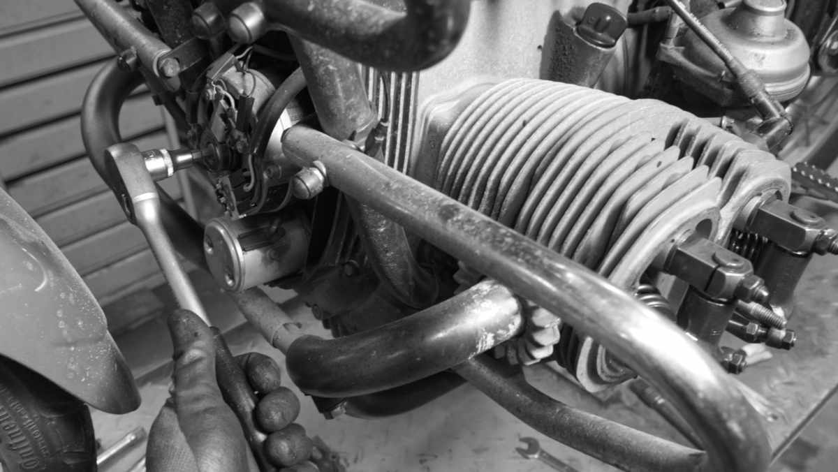
Where, on what and with what you turn the engine crankshaft naturally depends on the engine: In the case of the BMW, an Allen screw on the rotor of the alternator slip ring is a good choice. In car engines, the crankshaft pulley is usually suitable for this purpose. To prevent possible damage to the timing chain tensioner, the crankshaft must be turned the right way round. If in doubt, engage 5th gear and turn a drive wheel – the engine and valve train will then turn in the right direction.
With this cranking and a sharp look at the camshaft or the rocker arms, you notice that the camshaft only rotates at half crankshaft speed and the valves are closed most of the time. Only occasionally does a valve open and close tiredly, while the piston moves up and down in the combustion chamber.
So it doesn’t really matter where the crankshaft is positioned for our adjustment work – as long as the valves are not actuated, i.e. tight.
Check valve clearance
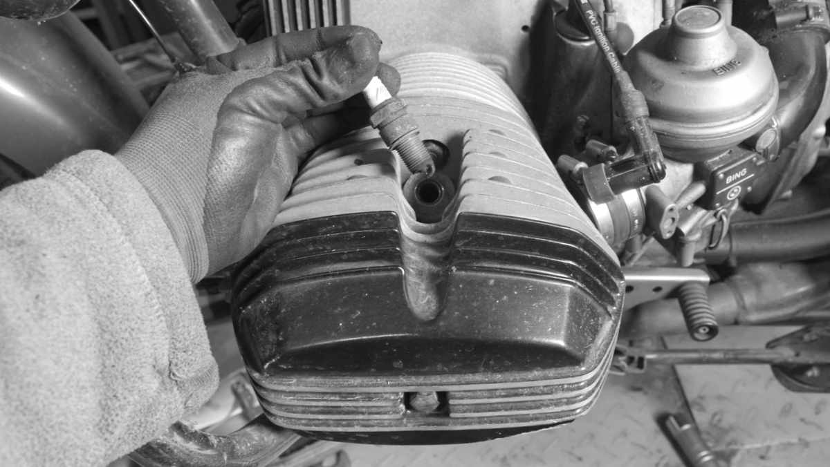
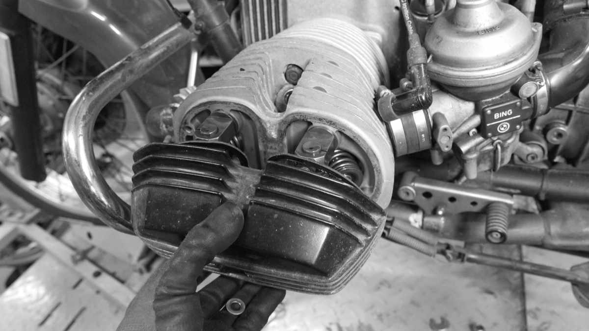
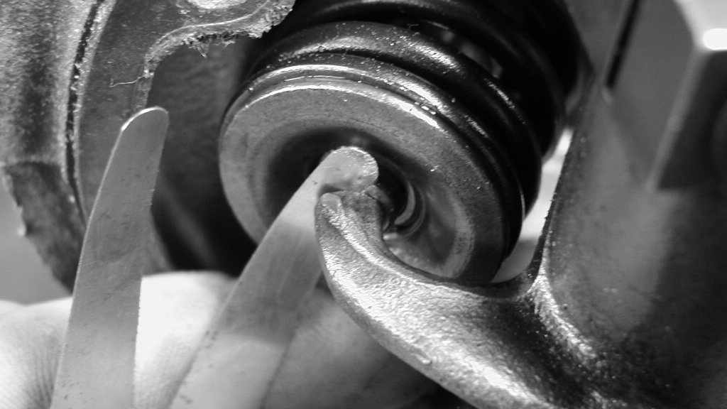
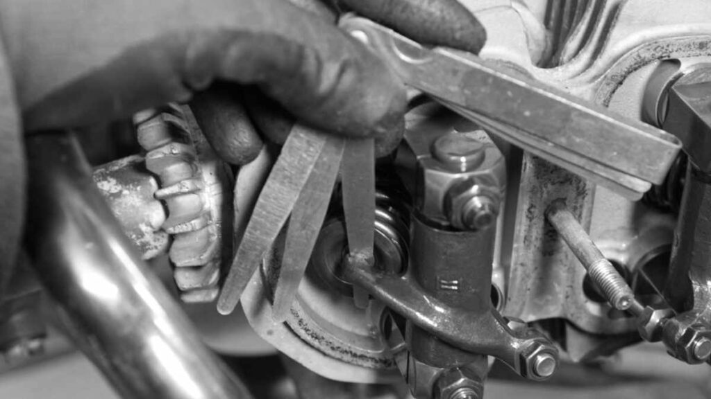
Once you have removed the spark plugs from the cylinder head, dismantled the valve cover and observed the ballet of rocker arms and valves long enough, it is time to finger between the rocker arm and valve head with the feeler gauge. Can the 0.2 mm blade be inserted in between? No? Not at all? Then perhaps the 0.15 mm blade? Neither? But then the leaflet with 0.1 mm. Neither?
Typically, valve clearances become smaller over time because the valve sinks into its seat and moves further in the direction of the valve train. It only does this very slowly and the valve clearance set at the last service appointment is usually still correct.
Adjust valves
However, if the test shows that the valve clearance is too small (or too large), it must be adjusted. To do this, open the lock nut very carefully by half a turn while holding the adjusting screw with a wrench.
The thread on these screws is often a metric standard thread and can therefore have a pitch of one millimeter per turn of the screw. To adjust by a tenth of a millimeter, 36° on the screw is enough – that’s just a little more than the five minutes between 11 a.m. and noon on the kitchen clock.
To increase the play, the screw is now turned out a little. To increase the play, insert a touch into the rocker arm. Because the feeler gauge compartments are usually rather coarsely graduated, checking and adjusting them is also an eternal compromise and a game of patience: If the target value at the inlet is 0.12 mm, the blade must slide loosely into the gap with 0.1 mm and the 0.15 mm should jam. But with a bit of smack you can still fit it in.
After adjustment, tighten the lock nut and finger the feeler gauge again: Is the play still correct? If yes: Tighten the lock nut properly, turn the engine again until the valve is actuated and then deactivated again. Check again. Clearence still correct? On to the next valve!
In principle, it doesn’t hurt to set the valve clearance slightly larger, because the valves will move into their seats until the next service appointment. Maybe it will only take half a day to get the 12-cylinder with 4 valves out of the hall. Helau!
