The ABS itself
The idea behind ABS is as simple as it is ingenious: instead of locking the wheel with a single brake application, the ABS system allows the brakes to “stutter” – the braking force is reduced several times per second and then fully applied again.
This allows the wheel to continue turning in the open phases and remains steerable; at the same time, slipping on slippery roads is prevented. ABS always decelerates the vehicle almost ideally, regardless of the condition of the tires and road surface. As the greatest possible deceleration (i.e. braking effect) occurs shortly before the wheel locks and the ABS provokes this point dozens of times per braking maneuver, braking performance on wet roads is also improved.
But where there is light, there is also shadow: an illuminated ABS control does not pose an acute threat to the lives of the occupants, but is a 100% NO-GO for the MTO guy: Light on, ABS out of order, no sticker. At the latest now the repair is due.
Structure of the ABS
A typical ABS consists of the following components:
Three or four (wheel) speed sensors
A brake pedal switch
The high-pressure block (or ABS block)
The control unit (often installed in the ABS block)
The lateral acceleration sensor (for systems with ESP)
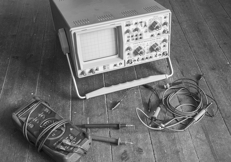
You can easily check the wheel sensors and the brake light switch yourself before taking the rolling doghouse to the workshop for expensive repairs and having the control unit read out. Not much more than a simple multimeter is needed for diagnosis in the workshop or in the light of a street lamp. If you own an oscilloscope, you are in an even better position. This is an excellent way of testing the wheel sensors.
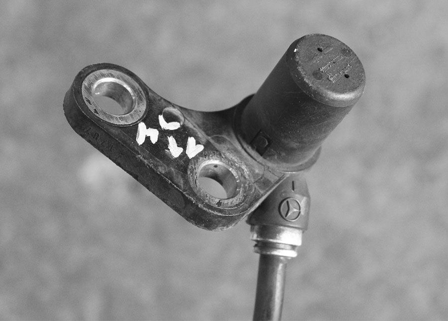
These little lollipops constantly supply the current speed of the wheel, from which the stutter frequency is derived. Older vehicles with “only” ABS (without ESP) are often built as three-channel systems. Such a system has one sensor per wheel on the front axle and a common sensor in the differential of the rear axle.
“Newer” models with ESP or ASR have four-channel ABS, i.e. one sensor per wheel.
Active / passive sensors
In principle, ABS sensors can be built as inductive sensors or Hall sensors.
Hall sensors cannot be tested in the way shown here; this will be covered in a later article. For this reason, only inductive sensors are referred to below.
Such speed sniffers are essentially small electromagnets, i.e. coils with several hundred windings with a tiny iron core. If the encoder wheel with its holes or slots rotates in front of this coil, this movement induces current – a rotating wheel therefore provides a clean sine wave. The length of the period is the rotational speed of the wheel.
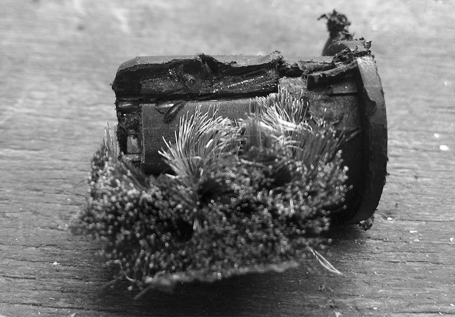
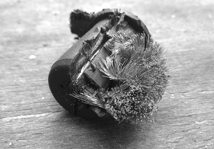
ABS sensors usually consist of the aforementioned coil in a plastic casing and a molded connection cable for the ABS control unit. This connection often becomes brittle over time, as does the plastic housing itself, which loses its plasticizers. Moisture can then penetrate and destroy the coil through corrosion – usually a hopeless case (for the sensor).
However, such a failure is relatively easy to detect. If the vehicle’s fault memory only returns the simple error message “wheel speed sensor” but does not mention the affected wheel, you can simply check the 4 corners of your beloved vehicle yourself.
Measuring with the multimeter / oscilloscope
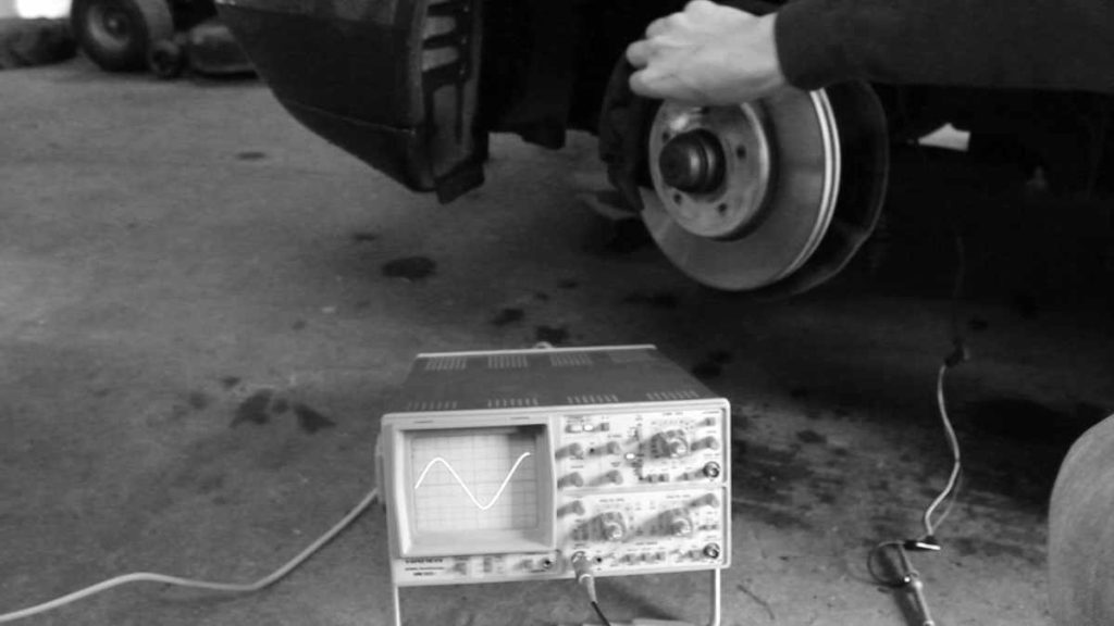
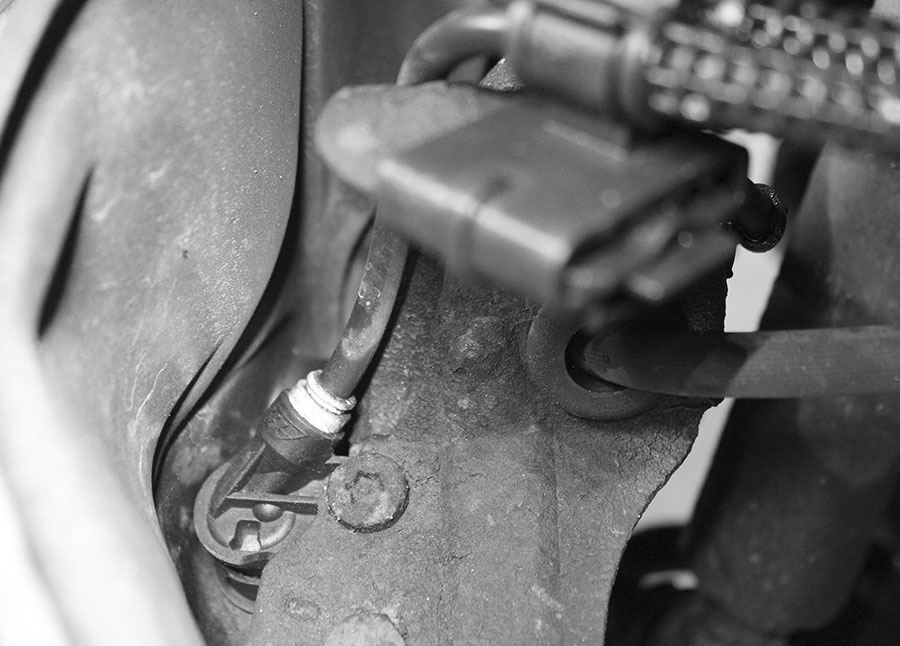
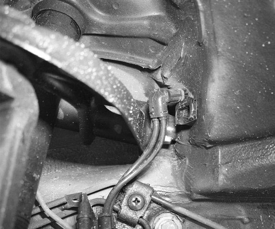
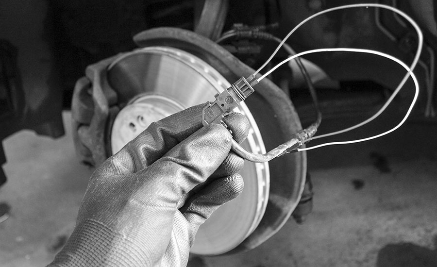
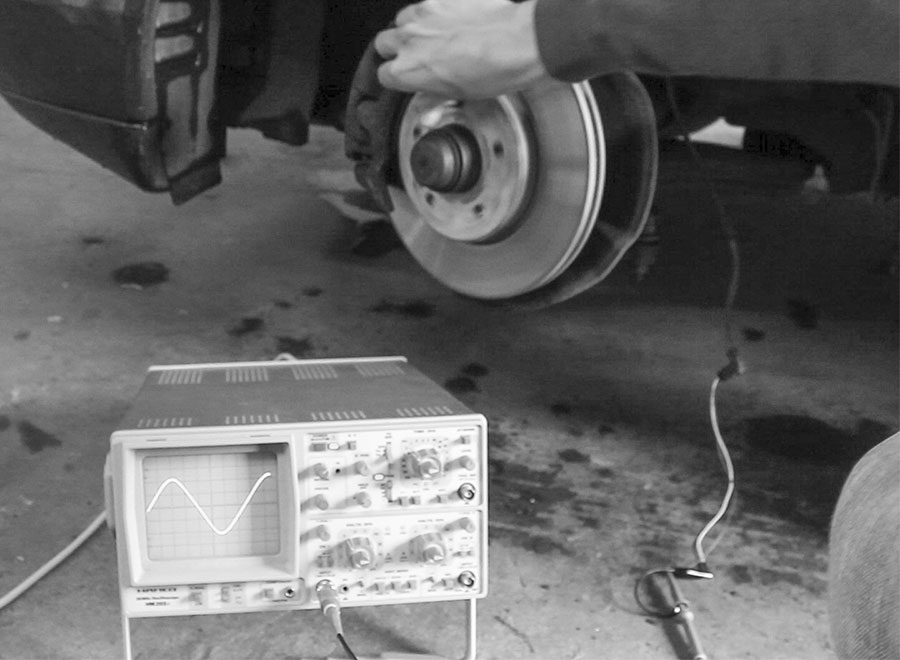
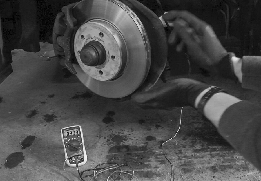
For this diagnosis, the vehicle is first jacked up, the steering is fully engaged and the cables in the wheel arch are disconnected – the cables are usually connected to those of the brake wear monitoring system. Once the plug is disconnected, it can be separated from its socket neighbor. For the test, the two contacts must now be connected to the multimeter or oscilloscope. Once the cable section is in place, the wheel is now turned by hand.
If you have set the multimeter to AC voltage, you should now see jumps in the voltage: Coil is working! As the pulses fluctuate rapidly in both amplitude and voltage, the standard multimeter can hardly display the data correctly, but this is not a problem as long as the jumps occur regularly.
With the oscilloscope, visual diagnosis is much easier – the wheel signal delivers a clean sine wave to the old tube screen, which was the state of the art in father’s best years.
If there is no signal (even if you have tried to rule out a possible loose contact in the cable) the sensor is dead. The coils are very sensitive to moisture and oxidize quickly. As a result, they lose their inner resistance and mutate into a short circuit.
Replace ABS sensor
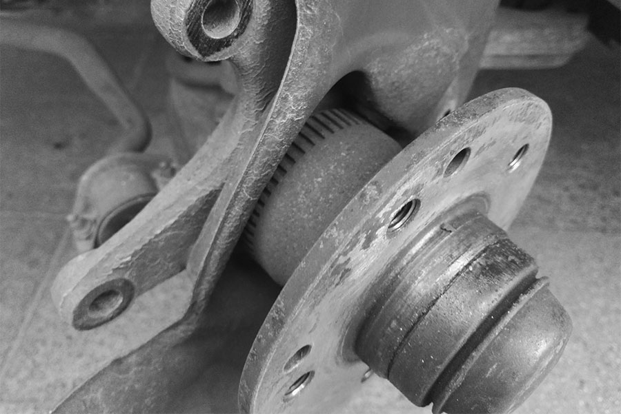
The coils generate their signal through a ring of teeth or a ring of holes, which constantly changes its magnetic field through its recesses. Each of these notches creates a “low”, while the tooth or the missing notch conjures up a “high” on the screen. If you have the wheel on display anyway, you can use this opportunity to clean the sprocket or ring gear to counteract any problems caused by abrasion of the disc brakes.
With regard to these encoder wheels, the manufacturers take different approaches – the VAG Group largely relies on an external ring gear that is attached to the outside of the wheel hub, while Mercedes and BMW use ring gears located in the wheel hub. The function and testing is the same in both cases.
Once you have found a broken ABS sensor and replaced it with a used one from a recycler, the classifieds or a brand-new model, it’s time for a test drive. Roll slowly on a safe route and then initiate an emergency braking maneuver. Is it stuttering again? Does the indicator light in the cockpit go out? Then your ABS will work perfectly again, yay!
On some makes, the fault memory must be deleted in order to reactivate safety-relevant systems such as the ABS system after a fault. This service is offered by both independent and brand-name garages and costs between 30 and 50 euros.

Letzte Aktualisierung am 2024-04-05 / Affiliate Links / Bilder von der Amazon Product Advertising API
